- Joined
- Apr 14, 2006
- Messages
- 23,055
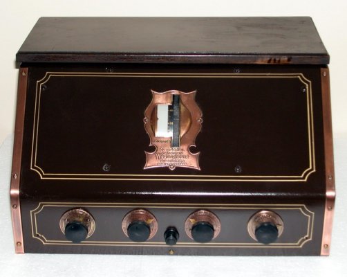
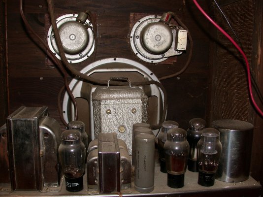
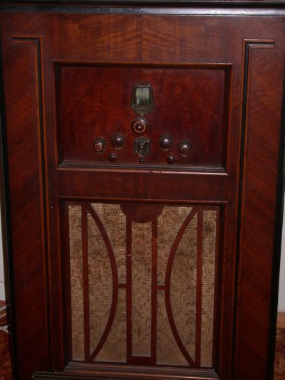
Today was the acid test for my latest electronic project -- resurrecting a 1936 vintage capacitor analyzer. When I first got it for $15, I found a loose mica capacitor in the wooden case and could not tell from whence it had come, which made me reluctant to do the old "plug it in and see if it works" trick.
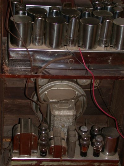
I didn't have a schematic, a parts list or a manual when I started. I was also unable to determine the proper values of many of the installed capacitors and resistors because they had no indication on them. So I had to get my old electrical engineering textbooks out of the attic and try to figure it out by inspecting the actual installed wiring and re-designing the circuit myself. My task was complicated by the fact that somebody had apparently tried to repair it before me and had screwed up the wiring in several places.
Eventually, I found a schematic on the internet, but it had no component values. I also found a manual, but no parts list. Eventually, I determined what the component values "should be" and then, by means of some internet search that I could not replicate if I tried, I finally found an old parts list. I was happy to see that the values agreed almost exactly with those that I had sussed out by myself.
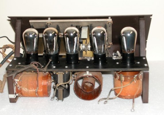
Yesterday was my day for disassembly, cleaning, component replacement and undoing the improper wiring. Then I put it away last night so I could sleep on it. After a final inspection today, I fired it up and, miracle of miracles, it works like a champ! I did the triumphant victory dance in the garage.
For those interested in electronics, it really is quite cool. It uses a Wien bridge to measure capacitance, using a "magic eye" tube as a null detector. It also measures leakage with a neon bulb relaxation oscillator. The DC power supply is an ancient 4-pin half-wave rectifier tube. It can also measure resistance using the bridge circuit. I tested all the old paper capacitors I had replaced and found, not surprisingly, that they leak like crazy, so it's a good thing I didn't just turn it on when I first got it.
I didn't have a schematic, a parts list or a manual when I started. I was also unable to determine the proper values of many of the installed capacitors and resistors because they had no indication on them. So I had to get my old electrical engineering textbooks out of the attic and try to figure it out by inspecting the actual installed wiring and re-designing the circuit myself. My task was complicated by the fact that somebody had apparently tried to repair it before me and had screwed up the wiring in several places.
Eventually, I found a schematic on the internet, but it had no component values. I also found a manual, but no parts list. Eventually, I determined what the component values "should be" and then, by means of some internet search that I could not replicate if I tried, I finally found an old parts list. I was happy to see that the values agreed almost exactly with those that I had sussed out by myself.
Yesterday was my day for disassembly, cleaning, component replacement and undoing the improper wiring. Then I put it away last night so I could sleep on it. After a final inspection today, I fired it up and, miracle of miracles, it works like a champ! I did the triumphant victory dance in the garage.
For those interested in electronics, it really is quite cool. It uses a Wien bridge to measure capacitance, using a "magic eye" tube as a null detector. It also measures leakage with a neon bulb relaxation oscillator. The DC power supply is an ancient 4-pin half-wave rectifier tube. It can also measure resistance using the bridge circuit. I tested all the old paper capacitors I had replaced and found, not surprisingly, that they leak like crazy, so it's a good thing I didn't just turn it on when I first got it.