Looking for advice on a pure sine wave power inverter

aja8888

Moderator Emeritus
Joined
Apr 22, 2011
Messages
18,742
Location
Conroe, Texas
For our upcoming SUV travel, DW needs oxygen on a constant basis. We have a portable Imogen One unit that provides 3 liters per minute of O2, but I would like to install a DC to AC pure sine wave inverter in the rear of the car to power our big oxygen concentrator. This is a model Invacare Perfecto2 V Five Liter Oxygen Concentrator With SensO2 Oxygen Sensor. This unit draws 325 watts or about 3 amps and weighs about 45 pounds.

There's a ton of inverters out there, but I know many of you are EE types and may have experience with particular models. I assume I will need one that will provide 500 or more watts and be wired directly to the car's battery.

Has anyone done anything like this? And have any recommendations for a particular brand of inverter?

Thanks!:)
 
I have had good luck with a Xantrex PROWatt SW2000 that I hard wired in my RV. Xantrex offers smaller similarly looking units SW1000 and SW600.

The SW2000 draws only 6W (0.5A) when running unloaded. That's really outstanding. The smaller units would draw even less in quiescence.

Be careful you do not drain the battery and not being able to start your car. An auxiliary battery along with an isolator would be safer.

10957314.jpg
 
Thanks folks. I was looking at 600 watt units since the load will only be 325 watts from the concentrator. But a 1000 watt will allow me more capacity. Next is determining wire size to run from the battery.
 
At 1 KW you will be pulling about 100 amps out of the battery.
 
I don't know what kind of motor is inside the oxygen concentrator, but induction motors can have a starting surge current 3x or 4x their running current. So, a 1kW inverter to run a 300W machine sounds reasonable.

The cable has to be AWG #2 at the minimum, and kept short between the battery and the inverter (~2 ft). The worse problem is that lead acid batteries have significant voltage sag when submitted to a continuous heavy load.

When I run the microwave oven in my RV which draws a bit more than 1kW, the inverter draws more than 120A from the batteries. Two marine 12V batteries in parallel can handle that for about 5 minutes when new. Two 6-V golf cart batteries in series cannot handle that at all: they have much higher internal resistance. I am using lithium batteries now.


Looking at the wire size table with the Xantrex unit, #2 looks to be about right. Unfortunately, in the SUV, the battery is under the hood and the O2 unit, as big as it is, will have to be located at the rear of the vehicle. Short cable runs creates a problem. This is not an RV where its pretty easy to have two batteries and be able to mount the inverter somewhere convenient.

It looks like I will have to somehow figure out a second battery configuration (at the rear) and have the Xantrex near it. :blush:
 
There's no need to have 2 batteries in the trunk. One, an AGM that's non-spillable, will run that inverter. AGM batteries have a much lower internal resistance than flooded batteries.

The next problem is to provide the juice from the alternator as no battery can supply the 325W load plus the inverter loss for long, unless you fill the trunk with lithium batteries.

Using AWG2 at 0.16 milliOhm/ft, assuming a run of 15 ft, you will have a resistance of 2.4 milliOhm. With losses through connectors and contact points, you will have more than 5 milliOhms easily. I am assuming that you can get a good ground through the vehicle chassis and avoid a cable for the return.

Then, the current requirement is 500W/12V = 42 Amps. With 5 milliOhms, the voltage drop is 0.2V, which is not too bad.

It's all doable.
 
Last edited:
To prevent the auxiliary battery in the rear from draining the starter battery and leaving you stranded, it is simplest to put a smart battery isolator between them. What this does is to connect them only when one has a voltage higher than, say 13.4V. This can happen only if the engine is running and the alternator is charging the starter battery. When the engine stops, the voltage drops, and the isolator disengages the two batteries.

This is better and much simpler than the isolator relay usually installed in RV's. This latter old type is just a dumb relay with its coil wired to the ignition switch. You can still drain both batteries if you leave the ignition switch on while the engine is not running.

The Xantrex inverter will shut down if the battery voltage drops below 10.5V. A battery in this stage may recover if charged up right away. However, a starting battery drained this low will have trouble cranking the engine.
 
Last edited:
One other thought is to also get a 110 v ac based charger with an included charge controller to maximize battery life such as this one (not a recommendation but)https://www.iotaengineering.com/12vdc.htm That way if you are near a 110 v outlet you can charge the battery while parked, as well as running the O2 concentrator from the 110 v.
 
To prevent the auxiliary battery in the rear from draining the starter battery and leaving you stranded, it is simplest to put a smart battery isolator between them. What this does is to connect them only when one has a voltage higher than, say 13.4V. This can happen only if the engine is running and the alternator is charging the starter battery. When the engine stops, the voltage drops, and the isolator disengages the two batteries.

This is better and much simpler than the isolator relay usually installed in RV's. This latter old type is just a dumb relay with its coil wired to the ignition switch. You can still drain both batteries if you leave the ignition switch on while the engine is not running.

The Xantrex inverter will shut down if the battery voltage drops below 10.5V. A battery in this stage may recover if charged up right away. However, a starting battery drained this low will have trouble cranking the engine.

Thanks, when I said a second battery, I meant one in the rear along with the SUV starter battery, not two back there. Xantrex (the pdf manual I downloaded) shows a diagram of the two batteries and the isolator and the schematic. Looking at the SUV, I believe I will need to install the cables under the vehicle as there is no apparent easy way to get them from the firewall to the rear.

I would guess a visit to an RV shop that installs these may be a better way to see how to do this rather than installing all this stuff myself. Looks like an "after the first of the year" project.
 
I'm no engineer, but is the normal car alternator going to be able to handle that load in addition to it's other normal loads?

When I was working police and ambulance vehicles all had special-order heavy duty alternators to handle the loads of the radio gear and all the lights.
 
One other thought is to also get a 110 v ac based charger with an included charge controller to maximize battery life such as this one (not a recommendation but)https://www.iotaengineering.com/12vdc.htm That way if you are near a 110 v outlet you can charge the battery while parked, as well as running the O2 concentrator from the 110 v.

That is a good idea. Thanks.
 
I'm no engineer, but is the normal car alternator going to be able to handle that load in addition to it's other normal loads?

When I was working police and ambulance vehicles all had special-order heavy duty alternators to handle the loads of the radio gear and all the lights.

Most alternators today are 90 amp or higher. The one in my VW diesel is 120 amp output. That should handle the load.

The O2 concentrator really only draws 325 watts or about 3 amps on A/C. So it's not a big continuous load. Interestingly, the 12V plug circuits in cars that you plug your cell phone charger into are rated for about 150 watts, so that wiring is not usable.

Big lights on ambulances and cop cars draw a lot of current, thus the extra large alternators, etc.
 
I have read all kinds of stories about RV shops. So check them out somehow before you give them the job.

I am not impressed with the wiring in my class C motorhome. And it was a factory job. Not too many RV manufacturers have the knowhow and quality control of big auto makers. RV shops may not be better.
 
Last edited:
I have read all kinds of stories about RV shops. So check them out somehow before you give them the job.

I am not impressed with the wiring in my class C motorhome. And it was a factory job. Not too many RV manufacturers have the knowhow and quality control of big auto makers. RV shops may not be better.

I still may do this job myself. The only difficult part is getting a nice, protected cable run from the car's battery to the rear area. Maybe I'll go to Best Buy and ask the stereo installers what they would do to get that cable run. I've used them in the past and they are OK. The rest is just hook ups and mounting the inverter.
 
Why don't you install the inverter close to the battery up front and then you just run essentially an extension cord to the rear. I've seen some people install them in the engine compartment, just depends on the space available and ability to keep it protected from the elements.
 
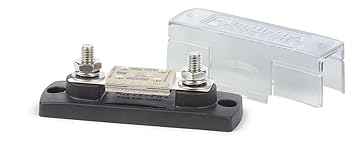
I would do the job myself. Some high-clearance SUVs have plenty of room under the chassis to run the cable. I would put two ANL 100A fuses, one on each end of the cable right at the battery posts. This prevents a short caused by cable chafing from escalating into a fire.

61oxR5G3IsL._SX355_.jpg


I would not put the inverter inside the engine compartment, definitely not this Xantrex or others like it. It has ventilation holes for cooling, and will not last long if dirt and water get inside.

Additionally, it needs cool air. Even inside my RV, this summer when I did some quick tests with my new lithium batteries, the inverter beeped to complain because I did not run the AC and the RV interior was at 110F.
 
For the smart isolation relay, you can surf the Web for VSR (voltage sensitive relay) or ACR (automatic charging relay). Easy to wire into that cable linking the two batteries. No need to wire into the ignition switch like the old isolation relay of RVs. No worry about forgetting like with a manual disconnect switch.
 
Last edited:
As I recall, a relay is superior to a solid state isolator as the solid state devices have a 0.7 volt drop. It is important to maximize the charging voltage for a secondary battery.
 
Why don't you install the inverter close to the battery up front and then you just run essentially an extension cord to the rear. I've seen some people install them in the engine compartment, just depends on the space available and ability to keep it protected from the elements.

I looked at the available space in the engine compartment and it is slim picking. My best bet is to locate it in the rear hatch area.
 
For the smart isolation relay, you can surf the Web for VSR (voltage sensitive relay) or ACR (automatic charging relay). Easy to wire into that cable linking the two batteries. No need to wire into the ignition switch like the old isolation relay of RVs. No worry about forgetting like with a manual disconnect switch.

Here's an image out of the Xantrex manual. The diagram on the left is what I believe is correct and it includes the VSR. Should I put a physical battery disconnnect switch in the circuit as a second disconnect? Plus add two 100 amp fuses, correct?

View attachment PROWatt SW Inverter NA.pdf
 
What travelover said earlier...

The schematic shows a diode battery isolator, not a VSR. This diode isolator diverts the alternator output to two batteries, and the batteries never "see" each other. The drawback of the diode isolator is that there's voltage drop from the alternator output to each of the two batteries that it feeds.

Diode isolators typically look like this, with 3 terminals and a big heatsink because the diodes get hot.

2-batt-1-alt-100-amp-max-battery-isolator-10.png


VSRs or ACRs are the newer breed. They have just 2 lugs that connect to the batteries, and a small ground terminal. They have an internal relay that is driven by a circuit that senses the battery voltage, then engages the relay to connect the two batteries when the voltage of the primary battery is high (meaning it is getting charged). The better VSRs can sense both terminals, so that you do not have to worry about which terminal goes to the primary.

Thanks for the explanation. All this is new to me since I have never dealt with inverters.
 
The long beefy cable that runs under the car if shorted to the chassis would cause a fire or the batteries to explode. That's why I would put an ANL fuse at each end of that cable right before it gets attached to each battery.

I guess a manual disconnect will not hurt and comes in handy at times if you want to remove the auxiliary battery and worry about the positive cable end hanging loose and shorting against the car body.
 
Back
Top Bottom