Backstory: After Thanksgiving, I pulled out of storage several LED C6 light strings that we purchased last year and displayed through December. Not surprisingly, a couple of the strings had lights out. After watching a few YT videos, I used a non-contract voltage checker to isolate the bad bulbs. On one string, a bulb needed to be re-seated. On the other string, two bulbs needed to be replaced. Those strings are working fine at the moment.
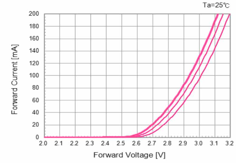
Now to the main reason for my post (I apologize if this gets a bit long). All of the C6 light strings we own, which includes the above, all have the same five colors: Red, Blue, Yellow, Orange, and Green. Based on what I have read, the Red, Yellow, and Orange LED diodes run at 2-2.2 volts, while the Green and Blue (also White) LED diodes run at 3-3.3 volts. These are usually in the 20 mA (0.02A) range.
I understand that all of the LED lights on most strings are not wired together in the same series. Usually the string is split up into two or more series wired in parallel. Which is why when a bulb goes out on an LED light string, only a portion of the string will go out.
But what if the LED lights in a series do not total up to 120 volts? I get that the addition of one or more resistors can compensate for this. I have seen resistors attached to the LED diode lead on each individual lamp. Usually, that isn't the case. I have seen some strings with what looks like an inline tube attached to the electrical wiring that I suspect are any resistors (I don't have any string like this - just what I've seen in the older videos).
So, if the LED lights in a series do not total close to 120 volts, if there are no resistors on the individual LED diodes, and there isn't an inline tube on the electrical wires which may provide resistance, how are the strings designed to handle it? And beyond that, is there any way to test a string to determine what voltage is being passed into each series of LED lights?
For anyone who technically understands this and can explain the concept further, I would greatly appreciate it.")
For everyone else, I apologize for the five minutes of your life you don't get back.
Now to the main reason for my post (I apologize if this gets a bit long). All of the C6 light strings we own, which includes the above, all have the same five colors: Red, Blue, Yellow, Orange, and Green. Based on what I have read, the Red, Yellow, and Orange LED diodes run at 2-2.2 volts, while the Green and Blue (also White) LED diodes run at 3-3.3 volts. These are usually in the 20 mA (0.02A) range.
I understand that all of the LED lights on most strings are not wired together in the same series. Usually the string is split up into two or more series wired in parallel. Which is why when a bulb goes out on an LED light string, only a portion of the string will go out.
But what if the LED lights in a series do not total up to 120 volts? I get that the addition of one or more resistors can compensate for this. I have seen resistors attached to the LED diode lead on each individual lamp. Usually, that isn't the case. I have seen some strings with what looks like an inline tube attached to the electrical wiring that I suspect are any resistors (I don't have any string like this - just what I've seen in the older videos).
So, if the LED lights in a series do not total close to 120 volts, if there are no resistors on the individual LED diodes, and there isn't an inline tube on the electrical wires which may provide resistance, how are the strings designed to handle it? And beyond that, is there any way to test a string to determine what voltage is being passed into each series of LED lights?
For anyone who technically understands this and can explain the concept further, I would greatly appreciate it.
For everyone else, I apologize for the five minutes of your life you don't get back.
Last edited: