Star Trek in the age of LED's

sengsational

Give me a museum and I'll fill it. (Picasso) Give me a forum ...
Site Team
Joined
Oct 13, 2010
Messages
10,766
We have a bunch of S/T ornaments that plug into the old incandescent strings (50 bulbs per 120 volt circuit). So I figure the ornaments expect 2.4 volts AC. The plan was to wire up a few sockets in parallel with a 2.4 volt AC transformer. But searching my box of transformers, the lowest they go is 5V, and I didn't find one online either. I thought about putting two in series with a 5 volt transformer, but I'm thinking that would lead to trouble. Ideas?
 
Sorry. Can't help you when it comes to electrician stuff, but when I saw the title of your post my first thought was William Shatner freakin out about the blinky lights in the Airplane sequel.
 
You were right that two lights in series across the 5V source could cause trouble. It might work OK, but only if the two lights had the same resistance. My ancient EE knowledge suggests you could build a simple voltage divider. Take two equal value resistors, at least 100kohms or so. Connect them together so you have three contact points: A (one end of resistor 1), B (where resistors 1 and 2 are connected together), and C (the other end of resistor 2). Connect A and C to your 5v source. Now connect your lights across A & B, and/or B & C. Either one should have 2.5 V across it. I’d recommend you split the lights across both AB and BC.
 
Last edited:
Thanks Gary. The last EE course I took was in 1978, and it seemed like "all theory", and none of it sunk in very far. My practical circuit designs since then usually ended with me letting the smoke out :)


I guess 5 volts across both resistors of 100Kohms each wouldn't have enough current to start heating up or over driving the transformer?
 
Here you go for next time
 

Attachments

  • Wire smoke.jpeg
    Wire smoke.jpeg
    29.4 KB · Views: 2
You were right that two lights in series across the 5V source could cause trouble. It might work OK, but only if the two lights had the same resistance. My ancient EE knowledge suggests you could build a simple voltage divider. Take two equal value resistors, at least 100kohms or so. Connect them together so you have three contact points: A (one end of resistor 1), B (where resistors 1 and 2 are connected together), and C (the other end of resistor 2). Connect A and C to your 5v source. Now connect your lights across A & B, and/or B & C. Either one should have 2.5 V across it. I’d recommend you split the lights across both AB and BC.

That doesn't work. You can't voltage divide like that with a significant unknown load because the load will change the divider resistance numbers.

Also, you would get negligible current through a 100k ohm resistance.

What you could do is use a 120 to 60v AC transformer feeding the 120v to 5v transformer. If you had such transformers.

Even easier though is to recognize that the bulbs will work on DC as well as AC, so you could just use a $0.30 adjustable voltage regulator to drop the 5V from your transformer down to 2.4v.
 
Last edited:
That doesn't work. You can't voltage divide like that with a significant unknown load because the load will change the divider resistance numbers.

Also, you would get negligible current through a 100k ohm resistance.

What you could do is use a 120 to 60v AC transformer feeding the 120v to 5v transformer. If you had such transformers.

Even easier though is to recognize that the bulbs will work on DC as well as AC, so you could just use a $0.30 adjustable voltage regulator to drop the 5V from your transformer down to 2.4v.

+1

I did find a few 2.4 ~ 2.6 V 'wall wart' power supplies online. Not cheap ($10~$20?) because they seem to be specialized for charging skil brand screwdrivers, or running a small motor, but that's an option. Be careful, a search for "2.4V" seems to come up with 2.4 AMPS as well, usually at a higher voltage.

A simpler option than an adjustable regulator: Take any 5V/USB type power supply, and just wire four plain-Jane rectifier diodes in series, connect that to the bulbs (wired in parallel). Each diode will drop ~ .6~.7V and can handle ~ 1A current. So 5V minus (4x.65) = ~2.4V. The drop across the diodes will stay pretty constant, regardless of the number of bulbs you connect, diodes have a very flat voltage-current curve.

-ERD50
 
Last edited:
Another, simple voltage divider option:

Use any 5V or USB style power supply. Wire two small identical type automotive bulbs (dome light type) across the 5V in series. The bulbs won't draw too much current from a 5V supply, as they will be at just 2.5V each. But they will likely be low enough impedance to balance out the load from the ornaments.

And especially if you alternate the ornaments across the two bulbs, it will even everything out.

https://www.amazon.com/SYLVANIA-2825-Miniature-Contains-Bulbs/dp/B01FWOCWNQ

-ERD50
 
Last edited:
Thanks for the Ideas, guys. I like the idea of feeding the output of one transformer into another, primary because I could try it today.

A question about working on DC as well as AC.... These Hallmark Star Trek ornaments were designed to plug into an AC bulb socket. I expect that inside the device, to power the circuit board, there's a rectifier, but aren't there different kinds of rectifiers that produce different DC outputs? And do we really know what the rectifier would do to the DC input?

The USB thing might be a nice option if DC will work.
 
Oh DC will work. The RMS value of AC is the equivalent of DC to resistive loads like filament bulbs. (this is why your AC is called 120V when actually the sine wave swings to about 170V (and -170V)
 
Thanks for the Ideas, guys. I like the idea of feeding the output of one transformer into another, primary because I could try it today.

A question about working on DC as well as AC.... These Hallmark Star Trek ornaments were designed to plug into an AC bulb socket. I expect that inside the device, to power the circuit board, there's a rectifier, but aren't there different kinds of rectifiers that produce different DC outputs? And do we really know what the rectifier would do to the DC input?

The USB thing might be a nice option if DC will work.

Tough to say w/o specifics. Are there motors inside? Some motors will need AC. But if it rectifying AC to DC, it may not be a problem (again, it depends - a circuit can actually be designed to work with the pulsating DC of a rectifier w/o any cap smoothing/filtering).

If it is a half-wave rectifier, you'll need to get the DC polarity correct. If it is a full wave rectifier, polarity won't matter.

[EDIT - but then again.... if it is rectifying the ~ 2.5VAC, AND it has a smoothing cap, the internal power might be the PEAK of the AC: 2.5VAC RMS * 1.414 = ~3.5V DC. ]. But if you give it something like the 2.4~2.5V AC, that will all be taken care of.

I like the idea of feeding the output of one transformer into another, primary because I could try it today.

Not sure what you mean by this? [EDIT - OK, I see Fermion suggested something like this earlier] Are you thinking of using something like a 120v XFMR with a 24V output to a 120V XFMR with a 12V output? So 120/24 = 1/5, and 120/12 = 1/10, so 120/5/10 = 2.4V?

If so, those have to be actual AC TRANSFORMERS. Many, many of these supplies these days are electronic switching circuits. But if they are pure AC, and fairly heavy/bulky, this might work.

-ERD50
 
Last edited:
Oh right. I DID say "AC transformer" but ERD is correct that a lot of the "wall wart" things you call transformers actually have various additional circuitry in them which mean they might not cascade.

A pure transformer is just coils of wire around a shared inductive path (typically a ferrous material like iron), no diodes or anything else.

I think playing around with dropping 5V usb DC to some lower value is the safer play here.
 
Last edited:
Most of the wall wart transformers in my box are real wire wound transformers...old and heavy. Most are AC. I've been throwing out devices for 50 years but tossing the wall warts into a box. About once per decade, I use one, LOL! If I set up a cascade, I'll test to see if it matches expectations.
 
So after I made the comments about specifics, and 'it depends', I thought, we need to know this stuff, we are shooting in the dark here.

So, search engine terms "Hallmark Star Trek ornaments run on a power supply"

turns up some hits. This guy has some specifics, he says that several years of these DO REQUIRE A/C (not DC), and are rated UP to 6VAC. But then he runs them at 6V AC, which I think is a little to close for comfort. But 6VAC is what you get on a 20 bulb string, so it makes sense that they should work on that with some margin.


https://hallmarkstartrekornaments.c...alternative-to-powering-your-old-ornaments-2/


EDIT (I keep having 2nd thoughts) - just because the ornament can plug into a 20 bulb string of 6V lights DOES NOT MEAN THAT THE ORNAMENT SHOULD BE RUN AT 6V!!!!! Those 6V lights will provide a current limit, the load of the ornament might actually clamp the voltage at something under 6V!

To put that another way - 6V directly out of a transformer is not the same as 120V from a string of 19 series 6V light bulbs! (or a string of 49 series 2.5V light bulbs). Might not make a difference, but then again, it might. And if the ornament is designed to provide less load than a bulb, it might even be working at a HIGHER voltage! We just don't know w/o a detailed schematic/information.

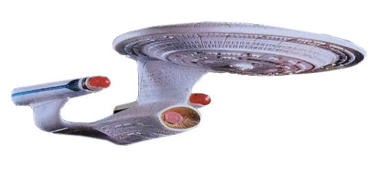
Can you give a link to the specific ornaments you have - I read that some of these talk or have sound effects - they definitely will be rectifying the AC to DC internally, maybe using both AC for lights, and this DC for electronics.


-ERD50
 
Last edited:
Do you have a sacrificial ornament, or equivalent, upon which you can test an implementation? Or maybe "It canna be done, Captain!" (wanted to post that three days ago but figured it more polite to wait until after there were helpful replies).
 
Some of the comments in this thread do seem to be pointing to the source as being current limited (as the bulb string would be), rather than just a fixed voltage.

https://electronics.stackexchange.c...a-new-power-source-for-light-string-ornaments

-ERD50

More reading, and yes, these ornaments are 'seeing' an AC current source (not 'voltage source').

Here's some clear specs on the miniature bulbs:

https://612vermont.com/2-5-volt-min...ndescent-string-lights-pinched-base-50-count/

https://612vermont.com/6-volt-mini-...lights-pinched-base-50-count-80-ma-0-48-watt/

You will see that the 2.5V bulbs are typically 170mA (0.425 Watts), and the 6V bulbs are at 80mA (0.48 Watts).

And the 3.5V bulbs are similar.

So inserting one of these ornaments into a 50 string of 2.5V bulbs or a 20 string of 6V bulbs will provide a current of ~ 80mA to 170mA with a source of 120 Volts (which will drop way down when the ornament is connected).

Note that 80~170mA @ 120V translates to 9.6 ~ 20 Watts (the total wattage of the sum of the bulbs), also calculated by 20 bulbs times .48 Watts (9.6 W), or 50 times 0.425 Watts (21.25 W).

So one approach would be to go right to 120V (if you are comfortable with mains voltage) with a 9 W to 20 W incandescent 120V bulb in series with the ornament to replicate the string of smaller bulbs. You could go with a lower voltage xfmr, and a lower series resistance, but the ornament voltage starts to play into it more.

But a 24VAC xfmr would supply 170mA max (into a short) with a resistance of ~ 140 Ohms, and 4 watts. So 24VAC and a couple 5W auto dome light bulbs in series would probably get you close.

Are we having fun? Or just buy some 20 bulb strings, and use those!

-ERD50
 
Last edited:
Do you have a sacrificial ornament, or equivalent, upon which you can test an implementation? ...

Some of these are no longer produced, from what I've read, no one want to sacrifice a single one!

Nothing says "Christmas" like a Star Wars ornament (I guess:confused:?)! Well, to each their own! :)


-ERD50-
 
Got a 2.8 VAC Rig

Thanks for all of those references. Good to know that they can stand up to 6 volts.

I guess it makes sense that there would be someone who crossed this bridge before me. And that they've documented their geeking out on it (given they're Star Trek fans, being geeky is almost a given).

I found a 12VAC and a 24VAC which in theory gives me 2.4 VAC in a cascade arrangement. I put a small load on it and tested it. Came out at 2.8 VAC. I have no idea what the load was, or if it was appropriate.

One of my ornaments has never worked quite right. It lights up, but the sound cuts off sometimes when the lights fluctuate. And it seems like it works better when first powered on, then later, doesn't play the sound at all. I wonder if it wasn't getting enough voltage. It's one of the coolest ornaments of all of them: City on the Edge of Forever. I hope that one works with the new power arrangement.

As to starting with a sacrificial sample, I'll start with the more boring ones, but I'm pretty sure that I'm going to be safe.

The problem now is that I threw out almost all of my 50 per circuit strings. I "know" I saved a few, but they're not obvious. Gotta keep looking and get out the soldering iron to make a multi socket parallel to add to the new pre-lit tree.
 

Attachments

  • cascade.jpg
    cascade.jpg
    46.5 KB · Views: 2
  • load.jpg
    load.jpg
    16.3 KB · Views: 1
I'm still concerned about the 'current source' (a higher voltage with series mini-light bulbs limiting the current) vs 'voltage source' (a voltage with low source resistance) for these to work well.

We could learn a lot if you got a working incandescent string. Plug in the ornaments as intended, and measure the voltage across it (strip the wires back a bit to be able to measure).

As I described, with a current source, each ornament might even be designed to work at a different voltage. As long as the current was in the range of a mini-light string, the voltage will 'float' as needed. Some ornaments might float to a relatively low voltage, some to a higher voltage. So you might end up with a situation where some ornaments work @ 2.5V, others don't.

Hard to tell the colors on that R you used for a load, Red-Red-Brown? 220 Ohms? You could measure it with your meter. If 220 Ohms, that is drawing just ~13mA, while a light string is ~ 80~170mA. So it tells you something, but it's not fully loaded.

-ERD50
 
If you do test it at a current approaching the 170mA, make sure to either use a minimum 1/2 watt resistor or multiple 1/4 watt (two 1/4 watt 220 ohm resistors in parallel is the same as a 1/2 watt 110 ohm resistor). Sorry if you know all this, just that those things get hot!
 
When I locate those few old light strings that I didn't toss, I'll measure the voltage across several of the ornaments. Good idea.

Also thanks for the intel on the resistor I tested with. I figured some load was better than none at all. I only powered it for a few seconds, but I'll keep in mind that if the current is up there, those things can get hot. I only kind of know the practicalities of this kind of work, so enough to be dangerous.
 
Some of these are no longer produced, from what I've read, no one want to sacrifice a single one!

Nothing says "Christmas" like a Star Wars ornament (I guess:confused:?)! Well, to each their own! :)


-ERD50-

I was given this one one Christmas, and am interested in this thread as I've changed to LED lights on the tree, and it would be nice to light up the ornament.

image19.jpeg
 
I'm still concerned about the 'current source' (a higher voltage with series mini-light bulbs limiting the current) vs 'voltage source' (a voltage with low source resistance) for these to work well.

We could learn a lot if you got a working incandescent string. Plug in the ornaments as intended, and measure the voltage across it (strip the wires back a bit to be able to measure).

As I described, with a current source, each ornament might even be designed to work at a different voltage. As long as the current was in the range of a mini-light string, the voltage will 'float' as needed. Some ornaments might float to a relatively low voltage, some to a higher voltage. So you might end up with a situation where some ornaments work @ 2.5V, others don't.
My original assumption, that these ornaments took their fair share of voltage was waaay wrong. As suggested, I got an incandescent string (50 per circuit) plugged in and working, then swapped in a bunch of ornaments, one at a time and measured the voltage drop across the device. Most were in the 8 or 9 volt range, so much higher than the theoretical 120/50=2.5. The lowest one was 5.8v and the highest one 13.6v*. I tried the rig I'd cobbled together based on my original assumption and it didn't operate even the least "needy" 5.8v device. So it's back to the drawing board.


BTW, I probably have every plug-in Star Trek ornament ever produced. It's not like I really WANTED them, but I probably showed that I appreciated the first one or two, then it became a tradition :facepalm:


* Wouldn't you know it, the highest voltage drop was the BORG CUBE!
 
Back
Top Bottom