427Vette
Recycles dryer sheets
I have been looking online and so far every diagram or drawing that I can find shows that the wire coming into the box is coming in above the switch.... so saying that crossing the wires inside the box is what an electrician would normally do.... I just do not buy it... It sounds like an easy out to fix the problem they created in the first place...
..
Well, I guess if that's what you found online I stand corrected. I mean if it's online it must be the gold standard and the way we are all supposed to be doing things. Or maybe the illustrator was just trying to simplify the diagram for those who actually need to look online for a simple schematic such as this.
I can tell you that most electricians will give minimal thought to the locations of devices in a box during the rough in stage of a project. At that point our concerns are usually more directed toward other challenges. One of my many concerns at that point is to make my wiring look super neat, straight and in order. For this to happen I don't want wires crossing over the top of each other as I strap them going down the studs. It's much more accepted to terminate them into the box where they then can be routed to the proper location to terminate onto the corresponding device. It is much neater to have the wires cross each other inside the box then externally.
I am sure if you express your concerns, state how much this obviously means to you and most importantly tell the electrician that you understand that he needs to charge you for his time in redoing what is already completed and presumably inspected, they will gladly change it for you.
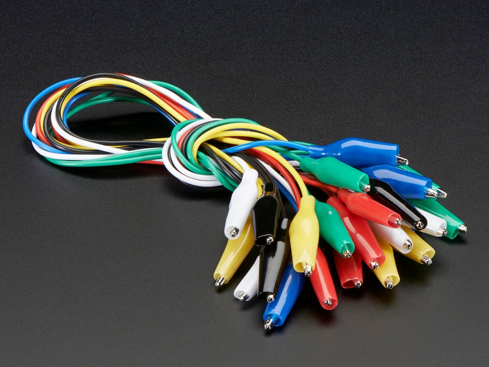
If you don't like the idea of wires crossing each other please don't ever remove the cover of your electric panel.
Regarding the junction box blank cover. It sounds like a good spot to put a combination CO/smoke detector. That way you can make it look like you meant to have it there.
 Really!?
")
 but, I installed a circuit breaker right at my battery terminal in my camper, so if a dead short happens somewhere in the main wire, the damage can be mitigated.