OP
OP
Souschef
Thinks s/he gets paid by the post
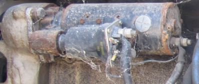
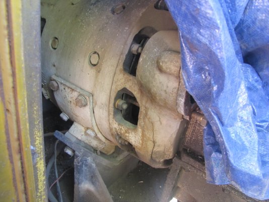
Dear ERD 50, This is the only working? diesel engine that we have. Your suggestion is valid if we had more than one, but sadly, that is not the case.I imagine you have other diesels with similar battery requirements, and that you don't run them all at the same time? If so, would some sort of wheeled battery cart work out, to share these batteries across a couple machines?
Or are you too much of a purist for that?
-ERD50
We are a very small railroad society, and do not have the many engines that places like the Pacific Railway museum does. If this one had not been donated to us, we would not have any.