How about some electrical help from you engineers

donheff

Give me a museum and I'll fill it. (Picasso) Give me a forum ...
Joined
Feb 20, 2006
Messages
11,346
Location
Washington, DC
I should research this myself but there is so much expertise relaxing away on this board I figured it makes more sense to appeal to you instead...

I have a low voltage light array triggered by a photo electric switch. A few years ago the switch failed and I found a similar switch at the hardware and got it going again. The transformer isn't coming on and I think the replacement switch has failed so I am going to replace it. When I disconnected the switch I saw that I had the black and white wires hooked up and the red wire unattached (there are only two input wires). Reading the labels on the switch they show BK-Line, WH-Neut, and Red-LOAD. I would have assumed I would connect the red and black wires in this case but white and black was working. What do those terms tell me (or rather, tell you)?
 
I would think that the black and white wires would attach to your incoming AC source. The red line goes to the "hot" side of the device you want to switch on. The device's neutral (white) would get connected to the switch's neutral.

photocell.jpg
 
Last edited:
Put a volt-meter on those wires. Do you have 120v or 220v across them?

Traditionally, "line" is in and "load" is out.
 
I was going to crack some well-worn jokes about "Is it plugged in?" and what ASS-U-ME means to an Engineer, but I'll behave. :angel:

I'm not an AC wiring expert, so I will refrain from guessing about the color coding for the wired connections.

Do you have a manufacturer and model number for the switch? Lots of companies put their wiring diagrams and installations instructions online, assuming [-]there, I went and said it[/-] you do not already have that paperwork in hand.
 
Do you have a manufacturer and model number for the switch? Lots of companies put their wiring diagrams and installations instructions online,

I'll second that. From your description, it is a little hard to tell if your application is designed for a switch on the line (120V) side, or the transformer secondary (low-voltage) side.

It does not make any sense that this could ever have been working properly w/o the red wire connected to anything - that would be the switched output.

-ERD50
 
I would think that the black and white wires would attach to your incoming AC source. The red line goes to the "hot" side of the device you want to switch on. The device's neutral (white) would get connected to the switch's neutral.

photocell.jpg

+1

Probably not working because the load wire wasn't hooked up. The switch will allow current to flow through the Load wire when on and shut it off when turned off. The White and Black wires provide power to the switch. When the switch is on it essentially connects the Black and Red wires together. Works the same for low-voltage 12V DC or AC, though not both at the same time, and the switch must be designed for the low voltage, not AC.
 
Last edited:
To OP, if you left the red wire unattached in the past, what other 2 wires the load was connected then?

The transformer isn't coming on

Before this happened, has the transformer ever been turned off by the PE switch before? Just curious.
 
From the description, both line and load are house voltage, with the output feeding a transformer, which drops the voltage to the requirement for the low-V lights. Not sure how it worked without the red wire connected...
 
To OP, if you left the red wire unattached in the past, what other 2 wires the load was connected then?


Before this happened, has the transformer ever been turned off by the PE switch before? Just curious.
The transformer box originally had a photoelectric sensor attached to two wires that connect to the box at terminals marked for "photocell." I assume the photocell generates a very low voltage signal that is received somewhere in the transformer box and when that signal drops to a certain level at dusk something (solenoid?) trips in the box and kicks the lighting transformer on. At that point a timer in the box turns the lights back off several hours later. When I replaced the photocell I used a photo electric switch with three wires marked as described. When I attached the white and black wires to the inputs it worked. I left the the red wire dangling. I probably have a device that does a couple of things and I am just tapping one of them.

The more I think about it, it was dumb to even post this. I don't really have enough info to solicit advice. I really need to figure out how to trip the solenoid or whatever controls this thing to find out whether the transformer even works. Then I can figure out whether the photocell is the problem or something else. I guess I could hook the photocell up to a multi-tester and figure out whether it generates a voltage in the sun -- at least that will tell me something.

Sorry for the distraction. If I get anywhere with this thing I will post the results. As to my electrical skills my history may be a guide. When I was a kid I built a Jacob's Ladder with a 15,000 volt sign transformer. When the spark stopped jumping the gap I grabbed the two rods to squeeze them closer. I will never forget how that worked out. :(
 
When I was a kid I built a Jacob's Ladder with a 15,000 volt sign transformer. When the spark stopped jumping the gap I grabbed the two rods to squeeze them closer. I will never forget how that worked out. :(

Ouch! I got hit by 480V one time and that hurt like h*ll! I've grabbed 120V many, many times in the past. Glad I am in management now and not doing the hands-on electrical engineering stuff any more. It's safer that way!
 
The transformer box originally had a photoelectric sensor attached to two wires that connect to the box at terminals marked for "photocell." I assume the photocell generates a very low voltage signal that is received somewhere in the transformer box and when that signal drops to a certain level at dusk something (solenoid?) trips in the box and kicks the lighting transformer on. At that point a timer in the box turns the lights back off several hours later. When I replaced the photocell I used a photo electric switch with three wires marked as described. When I attached the white and black wires to the inputs it worked. I left the the red wire dangling. I probably have a device that does a couple of things and I am just tapping one of them. ...

That makes more sense. I think you are correct - the 'box' is looking for a photocell sensor input, and then the 'box' does the switching/control.

You probably just got lucky that the switch you used, connected with just the black/white wires, provided enough of a change to trigger the circuit in the 'box'.

So I'd suggest you try to find the model number on that box, and find a suitable photo-sensor. They are probably generic, but it is possible that the box used a specific type of sensor with specific characteristics.

-ERD50
 
From what you wrote...

The transformer box originally had a photoelectric sensor attached to two wires that connect to the box at terminals marked for "photocell." ... When I replaced the photocell I used a photo electric switch with three wires marked as described. When I attached the white and black wires to the inputs it worked.

What happened here is that "3-wire" device that you bought as the replacement for the original "2-wire" device was not at all the same device as the latter. Yet, it mysteriously worked! So, how does one explain that?

Before I get to that, let's cover some background info first.

The original "2-wire" device is a simple common CdS (Cadmium Sulfide) photocell, which is also called a photoresistor. When in darkness, it appears as an open circuit. When light is shone on it, the photons knock some electrons "loose", and the device starts conducting some current. The photocell appears as a resistor, whose resistance diminishes as the light intensity increases.

...I guess I could hook the photocell up to a multi-tester and figure out whether it generates a voltage in the sun -- at least that will tell me something.

You would test it with an ohmmeter (not a voltmeter), and verify that its resistance goes down with exposure to light.

Following is a picture of this common photocell. Note that this type of photocell does not generate electricity as the solar cell in PV arrays.

LDR.jpg


Your low-voltage lighting transformer incorporates a small electronic circuit that senses the resistance of this photocell, and when the current through the photocell drops to a certain threshold, turns on a relay (what you called a "solenoid"). This relay is the switch that handles the high current that the low-voltage bulbs require.

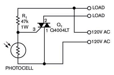
The "3-wire" device also uses the photocell. However, it incorporates a kind of transistor called a triac. The current through the photocell controls the triac, which itself switches the AC current through the load. This "3-wire" photo switch should be wired according to the diagram that timeasterday has posted.

So, how could this "3-wire" high-voltage switch work as a substitute for the original simpler "2-wire" photocell?

That brings us back to the original question that I posed earlier.

For the answer, let's look at a typical diagram of the "3-wire" device.

6670950f1(1).jpg


Note the top "load" wire is connected to one of the "120 VAC" lines. That is your white wire. The other "120 VAC" is the black wire (going to one end of the photocell and also to pin 1 of the triac), and the remaining "load" wire is the red wire (the one going to pin 2 of the triac).

We can see that by using only the white and black wires, you are wiring up to the photocell, but with a 47K resistor in series with the photoresistor. The triac is not used at all in this manner.

... I left the the red wire dangling. I probably have a device that does a couple of things and I am just tapping one of them...

What you surmised turns out to be correct! You only used the photocell of the replacement photo switch. Obviously, the circuit inside the low-voltage transformer is sensitive enough to work, despite the extra series 47K resistor. Note that in full day-light, the typical photocell resistance may drop to a few K Ohms, which is a lot lower than that 47K value.

By the way, Radio Shack has a pack of 5 photoresistors for $3.19. However, they are the "naked" type, and may get ruined with exposure to the weather. Also, the circuit inside the LV transformer isolates the photocell from the high-voltage AC, so it should be safe to handle the photocell. On the other hand, one should only open up the "3-wire" device to mess with its innards with extra care if the circuit is live.
 
Last edited:
I should research this myself but there is so much expertise relaxing away on this board I figured it makes more sense to appeal to you instead...

I have a low voltage light array triggered by a photo electric switch. A few years ago the switch failed and I found a similar switch at the hardware and got it going again. The transformer isn't coming on and I think the replacement switch has failed so I am going to replace it. When I disconnected the switch I saw that I had the black and white wires hooked up and the red wire unattached (there are only two input wires). Reading the labels on the switch they show BK-Line, WH-Neut, and Red-LOAD. I would have assumed I would connect the red and black wires in this case but white and black was working. What do those terms tell me (or rather, tell you)?
With 3 wires, it to use as three way switch. If you are using low voltage light with light sensor only, you only need to connect black and white to the you light source.


3-way-switch.jpg
 
Thank you NW-Bound, I now understand how these things work. The opposite of my guess.

I found some micro switches in the box and set the transformer to 24 hours on. Still doesn't work even with the the photoresister wires connected which should close the photo circuit as low resistance. I never heard the clunking (relay) sound the photoresister used to trip off when I covered it with my finger so my transformer is probably kaput. Still, I think I will did up some cheap standard photoresisters and see if that does anything before I give up.
 
So, how could this "3-wire" high-voltage switch work as a substitute for the original simpler "2-wire" photocell?

That brings us back to the original question that I posed earlier.

For the answer, let's look at a typical diagram of the "3-wire" device. ...

Thank you NW-Bound, I now understand how these things work.

Yes, excellent description from NW-Bound. I mentioned that the photo-cell must somehow be leaking some resistance change out to the Black-White wires, but his diagram nails it.

-ERD50
 
Thanks so much! Enjoyed the re-tutorial of EE 101....
 
By the way, Radio Shack has a pack of 5 photoresistors for $3.19. However, they are the "naked" type, and may get ruined with exposure to the weather.

Excellent analysis by NW-Bound. Spot on!
[FONT=&quot][/FONT]
[FONT=&quot]
[/FONT]

With a small dab of clear silicone caulk, these "naked" type photoresistors probably can be made weather resistant.
 
Solved

In the neverending saga of why I will never be a handy man I solved this problem or, more accurately, DW solved it. After setting the box to continuous on and still no lights I had concluded that the whole box was dead and was considering replacing the whole lighting system. This was a high end set but many years old. DW went out to the back yard to put up some Christmas lights and discovered that she had to reset a GPFS in the box on the deck and, voila, the lights are working again. I didn't even know there was a GPFS out there.
 
The correct way to wire this is the incoming (feed) from the power source should be white and black. Connect the white to white and the black to black. Also connect the white going to the (load) lights to the white. Connect the red to the outgoing line (load) to the lights.
 
because of the elements (water, etc) pretty much every outside electrical outlet is wired somewhere in line with a GPFS outlet. Same with bathrooms, garbage disposals, etc. In my case I have some GPFS's that are outside but have others that are actually inside that operate outside outlets.

The never ending search for the correct GPFS switch to trigger is always an adventure.
 
What is that old adage? When you hear hoof beats think horses not zebras.
 
Long ago, and far away, I worked for a hardware store. One of the more pleasant chores was to deliver new appliances. We wheeled in a new range, removed the old one, connected everything, then tried to fire the thing up, but nothing. Tripped breaker...
 

Latest posts

Back
Top Bottom