Well, what that capacitor is doing is correcting the 'power factor', the odd inefficiency in electrical power use when the net load your house presents to the electrical grid looks like a big inductor, rather than being a purely resistive load.
The size of the capacitor needs to be matched to the inductive portion of the load your house presents. (Hint: if the installer/salesman isn't doing this, you may be being scammed...)
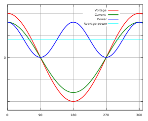
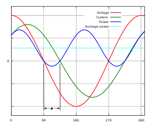
An inductive load like most electric motors, or older fluorescent light fixtures with magnetic ballasts will add a phase shift to the flow of power line current relative to voltage. Line voltage (in the US) oscillates at 60 times a second. With a purely resistive load, the voltage and current oscillate together, both peaking in one direction, at the same time every 60th of a second.
With a purely inductive or capacitive load, the voltage and current are 90 degrees out of phase, and no real power is consumed. This case is of concern in power distribution networks, because while that purely capacitive load uses no power, it draws real current through real wires, which have real resistance, and will consume power themselves. This reduces the remaining capacity for power carrying in the distribution network.
This is why electrical distribution networks will often have equipment in distribution substations to improve the power factor of their section of the grid.
A capacitor added at the mains entry to a home MAY improve power factor for the transmission line to the home. If you have a meter at the roadside, and a mile or two of transmission line to your home, with a consistent inductive load running in the home, one of these units might reduce your transmission line losses. It will not affect resistive losses on lines within the home to individual loads. You'll need to place capacitors, switched with each load, at the point of each load within the home.
Note that the resistive losses on the in-home wiring runs are very small.
Let's look at a washing machine. (Specifically, mine...) Out of a 41 minute cycle, the motor runs about 30 minutes, and has a power factor of 0.47.
- 30 minutes
- Power Factor: 0.47
- Current: 8.94A
- Real power: 513W
- Apparent power: 1081VA
Impendence phase angle is arcos(True power / apparent power) = 62 degrees
Reactive power = Real power * atan(phase angle) = 423 VAR
If the power factor for the motor was 1.0, we could have done this wash with a current of 4.66A, instead of 8.94. That is, the power factor added a 'phantom' current of (8.94 - 4.66) or 4.27A. That extra current produced real resistive losses in the wiring between the washer and panel.
Lets say we have 40 feet, wired in a 15 amp circuit (code sez #14 copper wire). #14 has 2.6 ohms per 1000 feet, so our 40 foot run is 0.104 ohms. Toss in the breaker contacts, screw connections, and whatnot, and call it 0.11 ohms. Let's see how much power our phantom current costs us.
Power = (I^2)R
Power = (4.27A * 4.27A) * 0.11 ohms
Power = 2 Watts
We ran for 30 minutes, or 1/2 hour.
Energy = (2 Watts/(1000 Watts/Kilowatt)) * 1/2 hour
Energy = 0.001 KWh
Now we need to know how much your juice costs. Let's say you're in California, sucking maximum juice from PG&E, so you're in a really high bracket for that last watt, 29.385 cents per KWh.
Cost = KWh * (pennies per KWh)
Cost = 0.001 KWh * 29.385 pennies per KWh
Cost = 0.029385 penny.
You're going to have to do quite a few loads of laundry to pay off that capacitor you installed at the motor.
And once again, no, the whole house 'KVAR unit' won't have any effect on this.
The National Institute of Standards and Technology has some good information on this:
NIST Team Demystifies Utility of Power Factor Correction Devices
There's a more detailed technical report (PDF) at
NIST Technical Note 1654, Regarding Electric Energy Savings, Power Factors, and Carbon Footprints: A Primer.

