Your recent repair? - 2021 to ?

Actually, they will need a new unit. Come to learn in the process that the compressor is 30 years old. I didn’t verify that but it is old. Amazing how the old appliances just keep chugging along.

Yes, the old systems can last a long time - at high energy cost though compared to new systems. It's like everything, trade-off of cost vs performance. We have a garage frig that was old house frig, that is now close to 30 years old and still working great. I am sure it uses a bit more energy, but it still works great.
 
Actually, they will need a new unit. Come to learn in the process that the compressor is 30 years old. I didn’t verify that but it is old. Amazing how the old appliances just keep chugging along.
At my last house, I had an AC unit that was at least 35 years old. In the 27 years I lived there, the only thing I ever did to it was to remove the contactor, and clean out all the dead ants. I finally replaced it, as other have said, because it was such a huge energy hog.
 
At my last house, I had an AC unit that was at least 35 years old. In the 27 years I lived there, the only thing I ever did to it was to remove the contactor, and clean out all the dead ants. I finally replaced it, as other have said, because it was such a huge energy hog.

Ours was at least 26 YO, it developed a leak, and I wasn't going to fix it at that point.

I did go high efficiency, variable speed fan, 2 stage compressor. Nice, but for the amount we use it ( we keep the windows open until the heat and humidity get to uncomfortable, and we are fairly tolerant), I don't think the savings would make up for the added cost.

When our current one (14 YO, just had the inside leaking coils replaced) needs replacement, I won't pay a lot for higher efficiency, just enough to hit the point of diminishing returns.

-ERD50
 
Friends with their baby came for a visit at my camp, in an older Toyota minimotorhome. When geetting ready to leave moho would not start. Tried jumping, no success. Start trouble shooting, battery good, no crank, no lights, not even emergency blinkers.

Hmmmm, I know nothing about Toyotas. Some head and butt scratching and thinking, must be a broken connection somewhere. Follow battery positive cable, some wiggling, nope, nothing. More head scratching and a few "our father" and other expletives expressed in thoughts.
Finally briiliant idea, check ground connection. In this model from battery negative, short cable to the fender sheet metal, flat washer and bolt. Another short wire from nearby fuse/relay box to another short wire to fender sheet metal, flat washer, bolt. No heavy gauge negative cable to engine block. Get some wrench to fit and crank down on the chassis grounding bolts. Flip hazard light switch, yes blinking. Try cranking, cranked, fired up. I suggested to them, that after getting home disconnect, clean, add star washers and electrical junction grease to these connections.

The negative terminal to fender sheet metal connections were corroded. Toyota, unlike GM which I am very familiar with used plain flat lugs and no star washers for the connection. In 50 years of car, truck ownership I never had a bad ground, apparently on Toyota and Dodge crappy ground connections are common.
Aye, live and learn.
 
Last edited:
I am in the middle of repairing one of my 2,400W inverters. Just a moment of senility, and I blew it up.

The DC/DC-converter stage got all 8 of its MOSFETs blown. No need to measure anything to know that, because their source leads were vaporized as if they were fuses. These CSD19505KCS transistors by TI are each rated at 150A continuous, 400A pulsed.

The rectifier diodes at the secondary winding of the high-frequency transformer have 2 out of 4 blown. Of course I am going to replace all 4.

The IGBT transistors of the H-switch that converts high-voltage DC to 240V AC seem OK. I only unsoldered 1 to check. Been debating whether to replace them all to be safe.

The MOSFETs and IGBTs are in short supply. I want to buy from a reputable source, not mom-and-pop AliExpress vendors, because desoldering/soldering in new ones is as painful as pulling teeth.

Finally found a good place that has them. Prices are not cheap, but I cannot afford cheap for this job.


PS. Total part cost: $59. New inverter: $430. I hope to be able to find all blown parts. For example, I discovered that the gate drive resistors of the 8 MOSFETs are also blown.


It took 2 weeks to receive the parts. I replaced the above devices yesterday, and tested out the inverter/charger operation with a lab power supply.

This morning, installed the repaired 240V inverter in the solar shed before it got too hot. It's back in operation to do its sole function of powering my bedroom mini-split. In the meantime, I had wired an autotransformer to get 240V power from 1 of the 120V inverters, while the kitchen outlets normally powered by this 120V inverter are auto-transferred back to the grid.

Before installing the MOSFETs, I carefully tested all of them. As mentioned, I decided to pay $4.03 a piece before shipping from a reputable Chinese vendor, while also bought 10 for $5.92 including shipping from a vendor on AliExpress. Big difference in price!

There are many parameters of a MOSFET that are not easy to verify, but the easiest and obvious ones are the gate threshold voltage and the full-on resistance.

The expensive MOSFETs all checked out at 0.0028 Ohm resistance, just like the specs. The cheapo MOSFETS are all 0.006 Ohm.

The cheap MOSFETS could have worked, assuming other parameters are comparable (a big assumption). However, they will dissipate 2x the power and run hotter. Not a risk I wanted to take.

Dang, it's hot out there even at 9AM. I have taken a shower, and lie basking in the cool air of the AC while typing this. Life is good.
 
Dang! What did you do? Lay a crowbar across some sections you shouldn't have? :(

+1
I'm also wondering , as new to this stuff and constantly think something bad is going to happen.
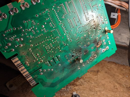
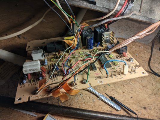
 :confused:


Here's my boo boo.

The inverter/charger was running, accepting power from the associated solar panels to charge the battery, and delivering power to the mini-split AC as its load. I looked at its display, and saw that it was actually supplying power to the AC from the grid, and not from the battery.

So, I switched off the 240V grid power breaker, intending to force the inverter/charger to transfer to battery power. BUT, BUT, BUT, in a moment of senility, I switched off the battery breaker to the inverter/charger.

The inverter/charger powered down. But when I flipped the battery power back on, sparks flied.

Post mortem analysis showed this. When the battery connection was lost while the solar charging function was running, the MPPT controller could not react fast enough to throttle back the charge. The internal DC voltage quickly rose from the battery voltage of 28V to the solar panel voltage of 60V.

I don't understand why the brain of the unit decided to turn on the inverter circuit, but it did. The DC-DC inverter portion is the stage that steps up the 28V battery to 350VDC, prior to the AC-DC conversion.

The MOSFETs rated for 80V were suddenly facing 120V, 2x the 60V from the PV panels. This is because the circuit used a push-pull transformer, with 4 MOSFETs in parallel driving each of the two legs of the primary. They all get shorted out due to the high voltage.

When the DC breaker was turned back on, the high current capacity of the battery bank vaporized the leads of all 8 MOSFETS instantaneously, even though they were 150A devices.

All this happened before the DC breaker of 125A could trip. It never tripped, because the shorted MOSFETs were instantly blown clear off.

Before the MOSFETs died, they worked long enough to drive enough power through the high-frequency transformer to fry out the 4 rectifier diodes on the secondary winding of the transformer.

Luckily, the 4 IGBTs of the H-switch that converts high-voltage DC to 240VAC had a rating of 650V, and they survived.

What I am still trying to figure out is how the 8 gate drive resistors of the MOSFETS were also blown up. The push-pull bipolar transistors driving the MOSFETS were still OK.
 
Last edited:
I always have utmost respect for DYIers that just go ahead a "tap a thread."


Great job!


I understand that. The photos are the repair of a cracked cast iron bell housing on a 1941 23 ton switch engine. Holes were drilled and tapped on both sides of the cracks, screw eyes were installed, and half inck bolts closed the cracks.
 

Attachments

  • IMG_6345.jpg
    IMG_6345.jpg
    576.3 KB · Views: 174
  • IMG_6344.jpg
    IMG_6344.jpg
    509.3 KB · Views: 23
.... The MOSFETs rated for 80V were suddenly facing 120V, 2x the 60V from the PV panels. This is because the circuit used a push-pull transformer, with 4 MOSFETs in parallel driving each of the two legs of the primary. They all get shorted out due to the high voltage. ... .

Could you get replacement MOSFETS with a 150V breakdown, just to protect against an issue (maybe from a fault rather than Operator Error)? Or are those just too expensive at the low Rds rating you want?

... installed the repaired 240V inverter in the solar shed before it got too hot.

When I first read that, I was thinking "he's going to wait until September?". :) Man, I just can't relate to living in those temperatures, but lots of people can't understand actually liking the 4 seasons, so to each their own. But I get a chuckle out of it!

-ERD50
 
What I am still trying to figure out is how the 8 gate drive resistors of the MOSFETS were also blown up. The push-pull bipolar transistors driving the MOSFETS were still OK.


It was actually simple. Because of the obviously manifested failure of the MOSFETs, I did not bother to measure them until now to satisfy my curiosity.

The gates of the blown transistors are no longer insulated from the source and drain, but fused to them. However, the measured resistance between the source and drain is 0 ohm, but between the gate and the source/drain is still around a couple of ohms.

Thus, the gate drive resistors were burned out as they were no longer driving a capacitive load, but nearly a short. If it weren't for the drive resistors of 10 ohm each that got burned, the driver transistors would also be blown out.


Could you get replacement MOSFETS with a 150V breakdown, just to protect against an issue (maybe from a fault rather than Operator Error)? Or are those just too expensive at the low Rds rating you want?


A 150A 150V MOSFET with the same low Rds costs $14/each. But more than costs, there are other reasons they should not be used.

High-voltage MOSFETs have a higher Rds, everything else being equal. Hence to reduce the resistance, they have to be of a bigger die. And that comes with the penalty of a higher gate capacitance. This would put stress on the bipolar transistors driving these MOSFETs. Even if the driving transistors do not fail, the switching speed will be slower, and causes more heat dissipation by the MOSFETs.


When I first read that, I was thinking "he's going to wait until September?". :) Man, I just can't relate to living in those temperatures, but lots of people can't understand actually liking the 4 seasons, so to each their own. But I get a chuckle out of it!

-ERD50


Well, places that have a better climate are plagued with other problems, such as earthquakes, wild fires, congestion, etc...

"If it's not one thing, it's 'nother" -- Roseanne Roseannadana
 
Last edited:
Actually, they will need a new unit. Come to learn in the process that the compressor is 30 years old. I didn’t verify that but it is old. Amazing how the old appliances just keep chugging along.

I have a rental fridge that I'm going to replace, it was manufactured in 1995, the tenant has been with us since 8/2001. She wore out 3 husbands, but not the fridge. She just bought a house.
 
I understand that. The photos are the repair of a cracked cast iron bell housing on a 1941 23 ton switch engine. Holes were drilled and tapped on both sides of the cracks, screw eyes were installed, and half inck bolts closed the cracks.

The keepers of the Liberty Bell could have used you.:D
 
a 1941 23 ton switch engine


A train engine. I remember in school taking a trip to someplace in Chicago that maintained trains. They had an engine opened up and at least in my memory the pistons were as big diameter as a 5 gallon bucket. Trains are cool.
 
a 1941 23 ton switch engine


A train engine. I remember in school taking a trip to someplace in Chicago that maintained trains. They had an engine opened up and at least in my memory the pistons were as big diameter as a 5 gallon bucket. Trains are cool.


That is probably right for a 1200 HP engine. Our little engine has a 6 cylinder 150 HP diesel.
 
That is probably right for a 1200 HP engine. Our little engine has a 6 cylinder 150 HP diesel.


My 1200cc Ducati I just sold had 135 ish HP. Brochure HP anyway.
I think they said about 86 foot pounds torque. Premium gas.

Bet your engine puts out a lot more torque. :D
 
How about this 4-story high diesel engine? It's mind boggling how they build something like this. I can't even imagine how they build a single piston.

This engine was built by a Swiss company, and went into a Chinese container ship. At 102 rpm, you will hear each cylinder firing. It's awesome.

The RTA96C-14 turbocharged 14-cylinder, two-stroke diesel engine is produced by Swiss company Wartsila-Sulzer, and it is the largest and most powerful diesel engine in the world today.

This 44 ft tall and 90 ft long diesel engine weighs over 2300 tons and can achieve a maximum power output of 108,920 hp at 102 rpm.


worlds-largest-diesel.jpg
 
How about this 4-story high diesel engine? It's mind boggling how they build something like this. I can't even imagine how they build a single piston.

This engine was built by a Swiss company, and went into a Chinese container ship. At 102 rpm, you will hear each cylinder firing. It's awesome.

worlds-largest-diesel.jpg

Wonder what the MPG numbers are for that monster…
 
I watched the videos on that engine, amazing. The engineer has to regularly climb up the ladders into the lower part of the engine to make the checks.


You have to heat the bunker oil, supercharge the intake air, cool the intake air after compression and inject with 3 injectors into each cylinder.

Ladders covered in oil and you have to climb up in there. Must be good pay.
 
Last edited:
Wonder what the MPG numbers are for that monster…

I saw some numbers like 200 tons of fuel per day, and the ship moves 600 miles/day. So, that's 3 miles/ton. This engine burns thicker fuel than diesel, but if we use the weight of diesel to compute, then a ton of fuel is 314 gal.

It works out to 1/100 of a mile per gallon. 53 ft/gal. Sounds like a gas guzzler, but it is not so.

Remember that Robbie's boat does something like 1 mile/gal, but the ship this thing propels is way way more than 100x the weight of Robbie's boat.

The container cargo on the ship is already around 300 million pounds.

I watched the videos on that engine, amazing. The engineer has to regularly climb up the ladders into the lower part of the engine to make the checks.


You have to heat the bunker oil, supercharge the intake air, cool the intake air after compression and inject with 3 injectors into each cylinder.

Ladders covered in oil and you have to climb up in there. Must be good pay.

It's mind boggling.
 
Last night at 10PM, I was still awake surfin' the Web in bed. Felt warm. Looked up at the mini-split and saw that it lost power. DANG! What now?

This is normally the time when the battery runs out of juice, and one inverter after another dumps its load back onto the grid. The transfer is in milliseconds, and unless you watch the light right then to see a quick blip, you would not know it. This time, the transfer did not happen. Or perhaps the repaired inverter failed again.

After groaning some, I grabbed a flash light to go out to the solar shed to check. Quickly found out that I did a bad wiring, which caused the transfer to not work.

Dang! I always hate it when I make mistakes like this. And I have been making more mistakes. Dang old age. I don't like it.

After 5 minutes to fix it up, I got the mini-split running again. Would have to turn on the central AC otherwise, but I prefer not to.
 
I wonder if it is possible to weld cast iron.


I understand that. The photos are the repair of a cracked cast iron bell housing on a 1941 23 ton switch engine. Holes were drilled and tapped on both sides of the cracks, screw eyes were installed, and half inck bolts closed the cracks.

attachment.php
 
I wonder if it is possible to weld cast iron.


Not really, you have to heat the whole thing up and cool it properly.


It is possible to weld cast iron, although it can be problematic due to the high carbon content. This carbon content is often around 2–4%, which is about ten times that of most steels. The welding process causes this carbon to migrate into the weld metal and/or the heat affected zone, leading to elevated brittleness/hardness. This, in turn, can lead to post weld cracking.
 
Yesterday evening I noticed the setpoint was 75F and the reading was 78F. Uh-oh. I was on my way to bed, so just flipped it to "off" and turned the upstairs A/C down to 75F (which, if it's not too hot outside, cools the downstairs somewhat reasonably).

I figured I had a freon leak, and it froze-up. But when I flipped the switch "on" this morning, I didn't hear the fan come on. Hmmm. So into the attic I ventured. When I applied power (I had left the thermostat to call for cooling), I could hear the blower relay click normally, but the blower didn't spin-up. I thought then maybe the capacitor on the blower motor went. So I disconnected the blower motor and hot-wired it directly to a 110 socket, and it spun up normally. So that wasn't it. It had to be the power wasn't coming off of the controller board. When I pulled it, I saw the problem...the connection between the blower relay and the line voltage had "blown up". In the picture, you you can see where the hi/low relay connection had blown up earlier, and I hacked it back to make that connection. I have no "after" picture, but I soldered a copper braid from the line to blower relay, and it's running again. This unit is the original in the 1993 house, and it's still limping along!
 

Attachments

  • PXL_20220721_160106259.jpg
    PXL_20220721_160106259.jpg
    725.9 KB · Views: 22
  • PXL_20220721_160057568.jpg
    PXL_20220721_160057568.jpg
    685.8 KB · Views: 16
Last edited:
^^^ I had a similar problem on a past vehicle, where the trace of a printed-circuit board was not properly sized to handle the current drawn by the AC blower.

It was pain in the rump to pull the dashboard to get to the doggone circuit board to solder in the jumper like you did. I cursed the guy who laid out that board.


PS. Why it took so long for the undersized trace to burn up?

In my case, I think it was because the blower motor got less efficient with time and drew more current as it aged.

In your case, I wonder if the relay right above the trace developed more resistance in its contact point, creates more heat which added to the trace demise.

PPS. This means, same as with people, inanimate objects get old and fail due to age. Nothing lasts forever.
 
Last edited:
Back
Top Bottom